Difference of signal outputs from different Sensors after same movement
Hello there,
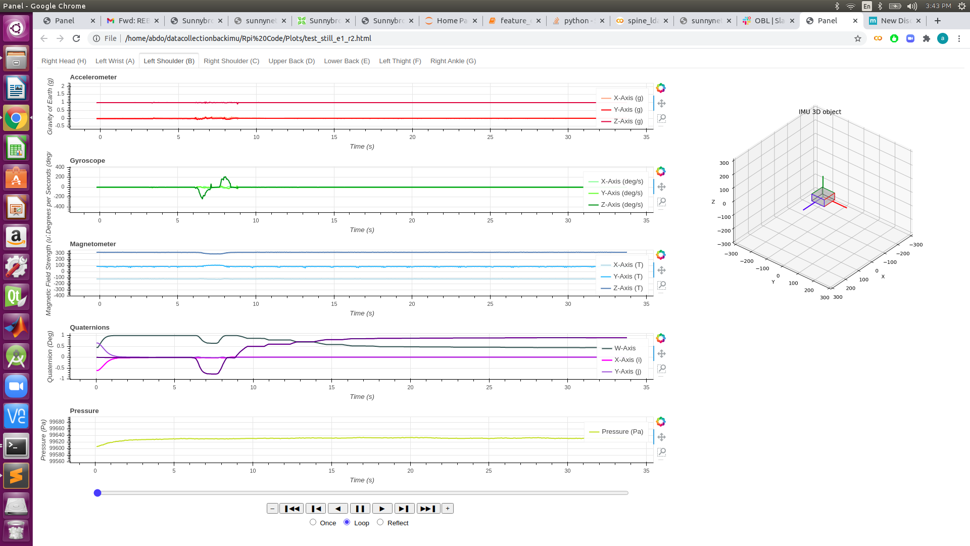
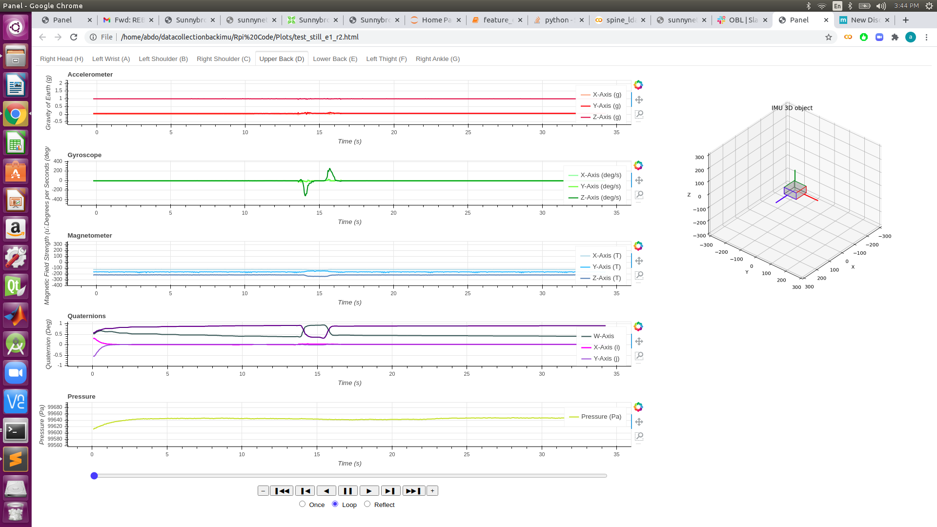
I have 8 sensors and I have calibrated them in the same exact way outside and I made them point in the same direction and then I only moved them 90 degrees to the right and returned them back to their original position along the XY axis. When I do this, the Acc and gyro signal data seem the same roughly between sensors (though there are some Acc offset for some sensor (E,F)). However, the Mag and Quat for a lot of the sensors are different and their direction of changes are different. Like their default offsets are different between sensors.
Do you know what could be the reason behind this? I have tried to try multiple methods to fix this issue but with no luck. I attached the html where you can look at all the 8 sensors and different signals with each sensor. I will also post 2 examples from the html file.
Thank you for all of your help.
Comments
You need to set the original orientation of the sensor fusion. This means that when you START the sensor fusion, the sensors must be in the same position (not before). You can also call our reset orientation API call.
This is because sensor fusion is relative to the starting position.
The magnetometer is likely affected by your surroundings. Even the battery affects the results. The magnets are extremely sensitive.
As for the orientation, they are all in the same orientation, direction, and position when I start the sensor fusion. Though I still get different results. I have tried to find the reset orientation API call for javascript but with no luck. Could you guide me to the specific API?
As for Magnetometer, I have calibrated the sensors outside in the outdoor so that there is nothing around it but as you can see the results are still distorted. If the only thing that is distorting it is the battery then the product will never output accurate magnetometer data? (because the battery has to be attached) Or do you mean that the battery level is what will change the result?
The battery will distort the signal, even just removing the battery from underneath the board (remove from the case and separate as much as possible will make a huge difference).
mbl_mw_sensor_fusion_reset_orientation() is what you need.
Okay thank you for posting the api, I will try it out and see if it works out.
For the battery, then there is no way that I can get accurate Magnometer even with calibration?
When I tried to use the api that you posted I keep getting that that command is not a function. Here is the specific error:
TypeError: MetaWear.mbl_mw_sensor_fusion_reset_orientation is not a function
Honestly,
It's tough to work with the magnetometer, there is almost always going to be strong fields/magnets around. All you can do is mitigate it as much as possible.
The reset orientation function is brand new (in firmware 1.5.1 only)
Okay thanks for the information.
I guess the magnetometer I can't do much about unfortunately. I guess the only way is to look at the changes which I hope will be the same.
As for the Quaternions, I have used the command as you have suggested (thanks again) but as I have attached with these new images, the sensor's Quaternions offsets are still off from one another. I have positioned the same manner, same direction, and same altitude and reseted the orientation after that. The data here just shows them staying still so that I can observe their offsets if there are any. What do you think could be the problem now?
After reviewing the forum some more it would seem the final option we have is to "tare" the signals. From what I understand, Taring is simply offsetting the signals with a specific value when the device is in a specific orientation,direction, and altitude.
So I guess that could be a simple and fast solution which would offset most of the sensors: Acceleromter, Gyroscope, Pressure. We could probably do the same thing with the Magnetometer without any problems.
Though I am not sure how applicable that will be for the Quaternions. the reason being is that the Quaternions jumps from 1 to -1 when it becomes greater than 1 and vise versa. That means that a static offset cannot be placed because the offset that was applicable when it was near 1 might make it go over 1 and same thing if it was a negative offset if it was close to -1. For example, lets say I want to offset to (1,0,0,0) but my sensor is outputting (0.9,0,0,0) in its taring (original) position. So the tar/offset that I would set would be (0.1,0,0,0) and keep adding this offset to all data I receive. But when the actual raw data outputs (1,0,0,0) I would be saving it as (1.1,0,0,0) which an incorrect metric in the Quaternion space.
I am not sure if this same problem is present for the Accelerometer, Gyroscope, and Magnetometer.
Any help or clarification would be much appreciated. Thanks
Also I have come up with the issue of Magnetometer. I was thinking that I would tare it when the Y axis is facing North and the X axis facing East. Though I didn't know what would be my reference (what are the values of X,Y,and Z that I want to be the idea defaults).
So for all the sensors, here are the defaults that I was going to use when the sensor is facing straight on a flat surface horizontally where the postive Y axis faces North, and the positive X faces East:
Acc:
Gyro:
Mag:
Quat:
Press:
Do you think that these defaults are correct along with my orientation? Also what should be the mag values?
The magnetometer is finicky because it's so sensitive.
Take a look at the differences in my iPhone compass app due to the magnetometer:
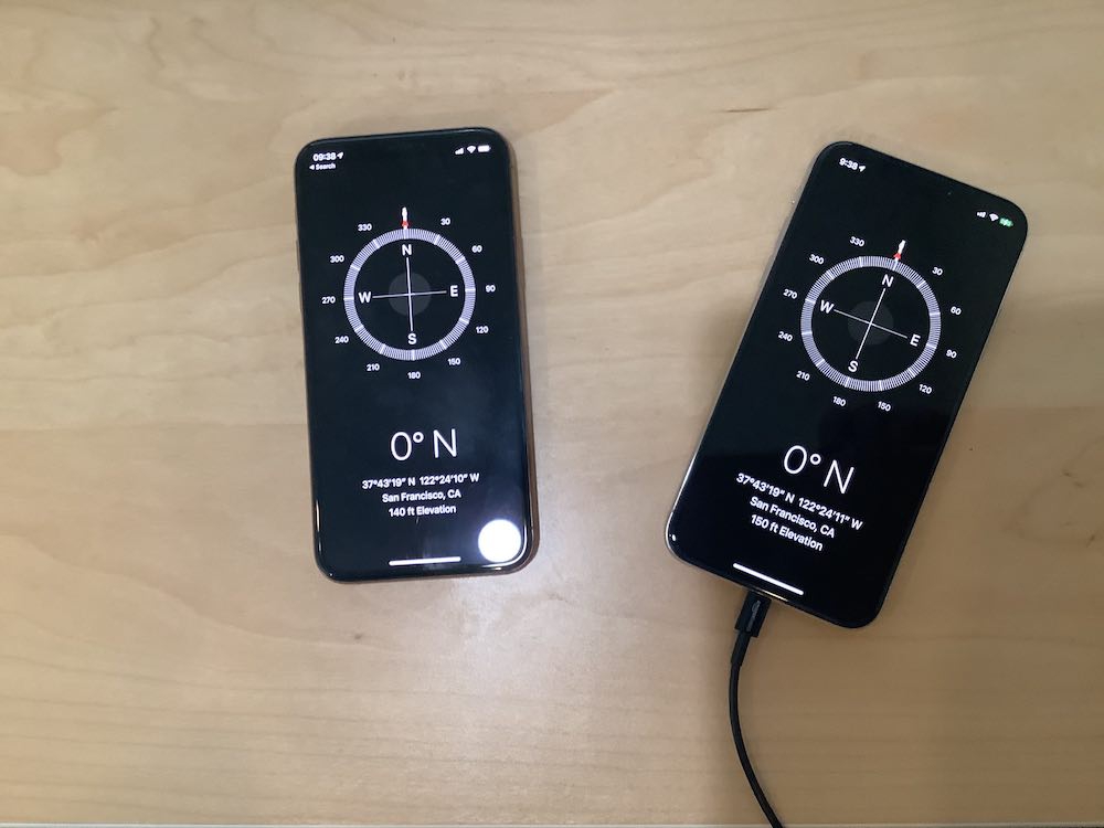
You can easily do this experiment yourself. My two state-of-the-art iPhones can't even agree on where North is!
In my experiment, I am using my iPhone and my Board and having them point North and taking data from the magnetometer:
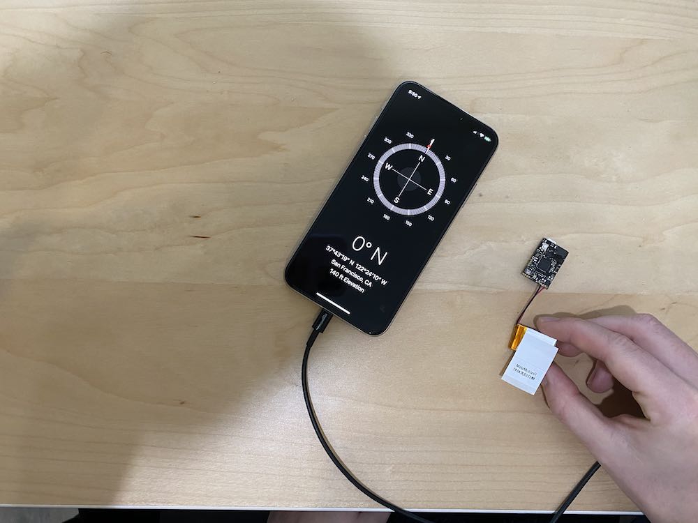
Data for the x-axis of the magnetometer pointing North:
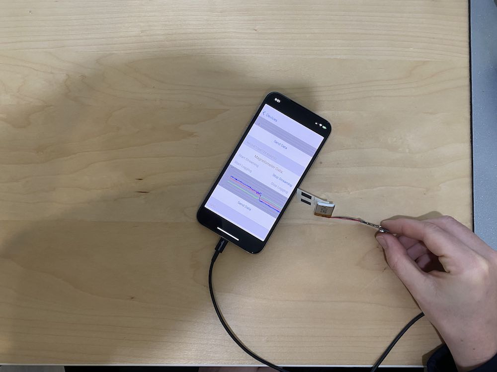
x, y, z Red line on the App
-0.75 -35.3 23.8
1.43 -37.6 15.9
0.00 -36.1 23.1
-1.5 -38.0 20.1
0.0 -35.7 19.6
Data for the y-axis of the magnetometer pointing North:
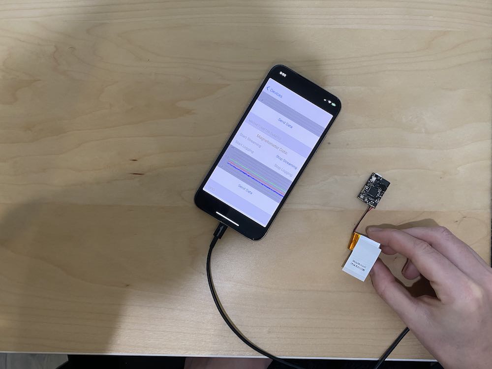
x, y, z Green line on the App
-25.5 3.00 -43.1
-19.9 1.50 -46.2
-24.0 1.875 -44.7
-22.1 -0.68 -44.7
-23.3 2.21 -50.4
Data for the z-axis of the magnetometer pointing North:
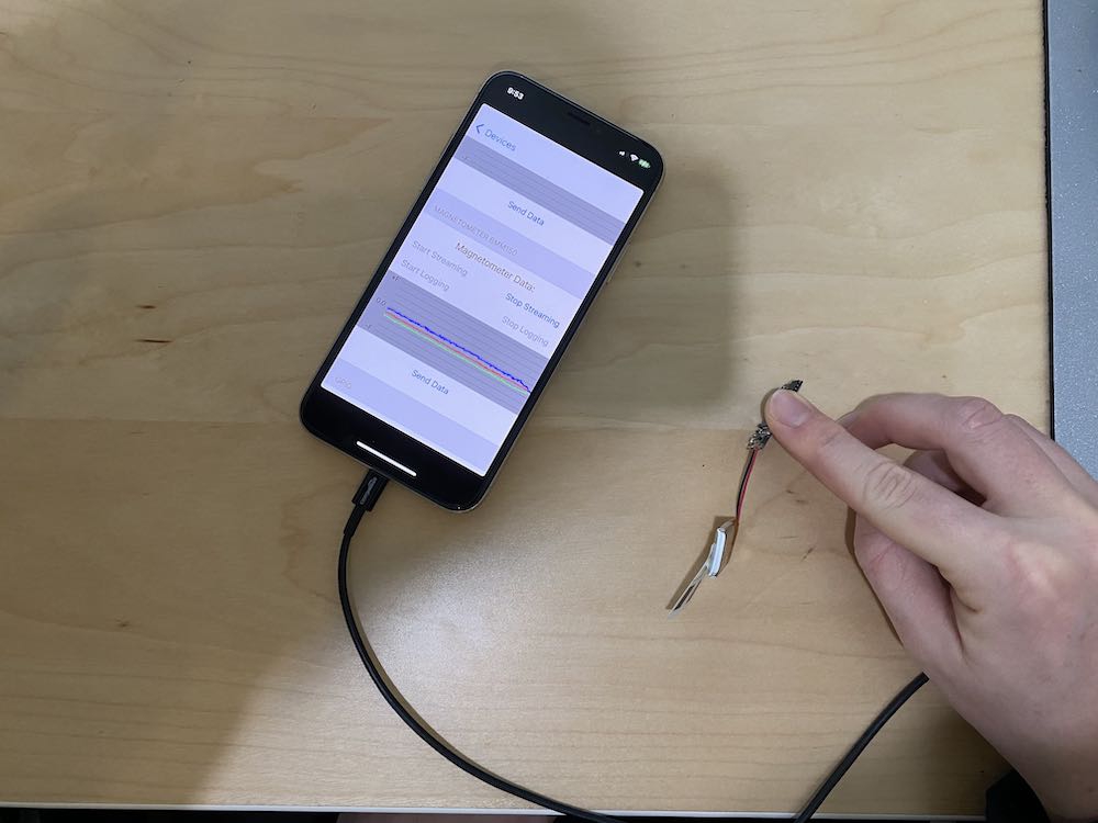
x, y, z Blue
line on the App
-20.6 -35.0 -2.62
-18.5 -35.4 -0.75
-18.8 -35.4 -0.75
-19.2 -35.4 -4.56
-21.0 -35.4 -0.75
Thank you so much for this data. It is much appreciated
What do you think about the Quat, I don't think a static scalar will actually be a correct method to offset the reference to 1,0,0,0 as the Quat is a vector. So would I need to find the rotation subtraction between 1,0,0,0 and my incorrect default and rotate it by that subtraction amount with each new data entry I receive?
I hope I am making sense here...
Just to show that when I use the API, or the inherent reset of the Quaternions when I start/stop Sensor fusion, it right away goes back to its drifted Quaterion values as shown in the below picture (Of course I am not moving the sensor at all). You can look at the file I have attached for more detail.
Yes, you make sense.
I think if you use Quaternions you can simply multiply them (multiply tare quaternion with incoming raw quaternion).
Ow so it is a simple multiplication? I will try it out.
Also, after reviewing the datasheets of the sensor you have used and the tutorial, aren't the orientations that you have used in these illustrations incorrect? Its just because I need to make sure they data that your provided is correct if I wanted to use it to tare the magnetometer values with a correct reference.
The orientation are for the bmi160, not the mma.
So I actually now 5 questions, any help would be greatly appreciated:
1: This question is related to your reply:
Now from what I understand, that means that the orientation of the bmi160 (Acc & Gyro) and bmm150 (Mag) are different within the sensor? If so, I have seriously tried to multiple times to draw out its orientation based on the MMR (Which I think would be the same on the MMC If compare it with the bmi160 coord) but no matter if I consider the force being horizontal (.ie front) or vertical (ie. upward) the coordination don't work out with me. I have tried to compare the bmm150 orientation to the orientation of bmi160 but seriously couldn't. If you could just elaborate on this as I have tried to look at the bmm150 datasheet from the bosch main website but this wasn't useful because both components are integrated together into one element (bmi160 & bmm150) and so I can't visualise it individually to compare the illustrations with the one from the bosch website. Maybe a drawing could help?
2: From what I got from your mag data is that when the positive axis (whether x,y, or z) is facing north, it will output zero and second axis will be output roughly 20 and the third roughly in the 40 range.
Now when I compare it with my readings, the range of my data is way bigger. What I mean is that when I try to position the MMC (y axis) to North with the coordination of BMI160 (I know I should be using BMM but lets just use that for now) I get ranges from -300 ->
301. This is of course for all sensors but individually some output from 0-300, 20-160, -20- -300, and so on. This could be due to the range settings that I have put which is NDOF for sensor fusion. If so, what do you think would be the ideal output for my ranges? Or is there any way to fix it?
3: As for taring the quaternion , I have tried to search through the forums and google. After that and some try and error, this is the code in javascript that I have come up with to tare the quaternions:
Please if you can confirm that my methodology is correct or not. I am now sure.
4: What should I use as the default value of the pressure sensor (Barometer) when there is nothing putting pressure on it (its inside the case though)? I thought it would be roughly 99600 (in Pa If i am not wrong) but I am not sure if that is the default value. Or is it just atmospheric pressure (101,325 Pa)? Its because my readings are below that number if you take a look at my files that I have posted before.
5: If you go back to the very first post in this discussion ( the one that opened it), and If you examine the pictures where I only rotated the senors 90 degrees to the right along the XY axis (horizontal), you realise that the X and Z axis of the quaternions for all the sensors stay stationary which makes sense. However, when you observe the W and Y axis, for 7 sensors those axis decrease and go back to their original position. However, for sensor D, the Y axis does go down but the W axis goes up .... I know Quaternions are hard to understand and comprehend but I mean I would think that I should see the same change of difference with sensor D as I have seen with the rest of the sensors.
Do you have any idea would could be the cause. Please ignore the offsets of the axis between sensors as that is what I am trying to fix with taring each sensor (and each signal). But for the change of signal to be different for the same movement, that is worrisome. I have tried to repeat this test and if I remember correctly the same phenomenon has occurred. Any input in this would be of great help. (Remember that they are all in the same orientation and direction in these tests)
1: Can you please provide an illustration that shows the difference?
2: Okay I will test for my self when I understand the orientation of the mag
3: ... umm my whole previous posts were talking about how the reset orientation API doesn't work. Please read my last post which contained a picture. The reason why I am taring is because the reset API doesn't work so the only work around left is taring it through software. So, is my my taring methodology for the qauternions correct?
4: I guess the only thing that I can use then is the change of the pressure sensors if I don't tare all my 8 sensors to the same offset. Also, I will go with the settings I have as I don't think I will have any different results if I change the settings. I have tried to play around the setting and read through API long enough.
5: I understand, but that wasn't the question. An opposite change in only one axis of the qauternions definitely means a different orientation. Look at the pic that I referred to and you will understand what I mean. So do you have any other ideas what it could be?
3: It would seem that my taring for the quaternions is wrong. I have tried to test it with this visualisation tool online and it doesn't seem to coincide with my tests.
For example, I made a taring angle of 30 along the y axis, took the corresponding quat and puts those as my original taring coordination. Next I moved 20 degrees along the x (now 30 degrees along y and 20 along y) and took that quat and put it as my new raw coord (t in my code). After I ran my code I compared it to the value if I only had moved 20 degrees along the x axis (x:20 y:0 z:0) and unfortunately that quat doesn't match the quat that was outputted from my algorithm. I am not sure, I could be doing something wrong.
The math is:
tare correct quat = (first tare coord x (new raw coord)^-1).normalize
Any ideas on the quaternion taring algorithm. It seems simply ( new raw quat x tar) doesn't give me the corrected coordination. Any help would be much appreciateed.
@abdalrahman9,
I'm not much of a quat expert. I recommend finding a good tutorial using google-fu to learn to manipulate quaternions.
Okay I will try my best as I have already read most of the content online related to Quaternion manipulation and multiplication.
As for the Magnetometer, after I have read the BMM150 datasheet and using the below reference picture:
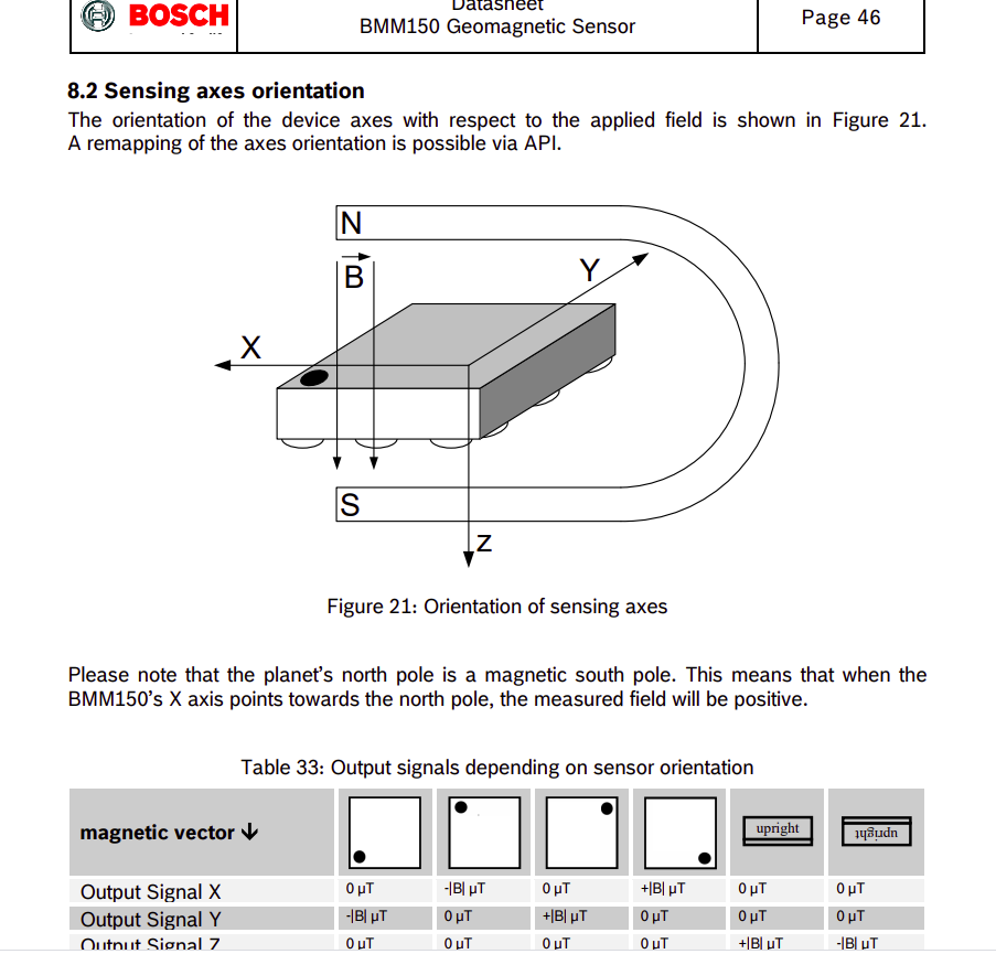
I positioned the sensors in the position as were outlined in the outline:
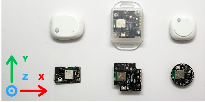
where the positive Y-axis of the sensor shown above is facing north, the positive X-axis is facing East, and the positive Z facing upwards
The data I got from all my 8 MMC sensors for that same orientation is shown in the below table:
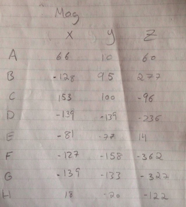
You can see that the data is all random and there isn't really any relationship or commonality between the sensors.
However, after studying the Magnetometer signals from any of the files I have previously posted (the mag axis order of the data for each sensor is the same ... constant) I have realized that the majority (5/8) have the X and Y axis roughly always close together and the Z axis below those 2 axis with a difference of -100 usually.
So, using the picture I have posted for the BMM150 datasheet as reference (Thinking the BMM150 is in the orientation of the last column in that table .... the BMM150 is upside down in reference to the mag force when I have my MMC orientated as in picture 2 in this post (the tutorial pic)) I tared my Magnetometer data to the following values:
Mag X axis: 0
Mag Y axis: 0
Mag z axis: -100
Do you think that this reasoning is correct along with my taring values? I have tried my best to make out the reasoning why my data looks the way it is so hopefully this is correct. (Same results when I am outside in the open without any devices around)
Just remember the mag is not in the same orientation as the gyro/acc.
I don't have time to look at everything right now since I am working on the MMS release but I think you are on the right track.
Yup, I understand that the Mag's orientation is different from the gyro/acc.
Okay thanks for the response. If you do get the time, then I would appreciate the more detailed response.
Hopefully the MMS release will go well!
@abdalrahman9,
Again sorry, the MMS is taking up all of my time.
When this is done, maybe we can work together to write a documentation section on how to tare the sensors in hardware and software.