Sending non-standard i2c command to external i2c slave device

Hey everyone,
We are playing around with the MetawearR, trying to interface to MPU6050.
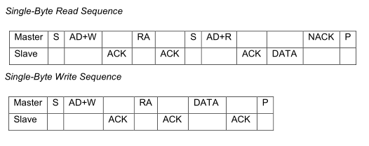
We have no problem reading a single byte from it and writing a single byte to it using:
"mbl_mw_datasignal_read_with_parameters" and "mbl_mw_i2c_write" functions.
The snapshot below is from the MPU6050 datasheet: (Its read/write sequence is pretty much same as a standard i2c slave device)
Now we are trying to interface the MetawearR with the MS5803-14BA.
The i2c communication procedure for MS5803-14BA is shown below (snapshot from datasheet)
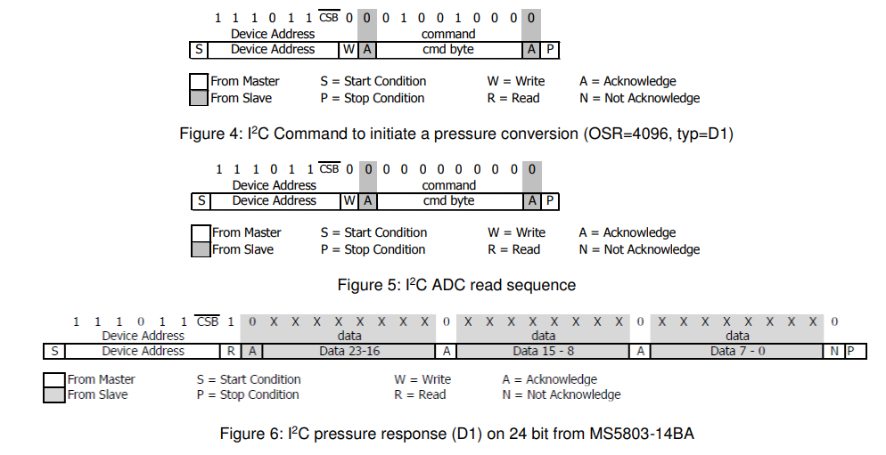
So to get a reading from it, we need to do three steps -- shown above from "Figure 4" to "Figure 6".
The steps are totally different from the ones for MPU6050 or any standard i2c slave device.
Just wondering how do we use the "mbl_mw_datasignal_read_with_parameters" and "mbl_mw_i2c_write" functions to do those steps?
Cheers,
Blake
Comments
Hi Blake,
You're right, the MS5803 interface is a bit unconventional.
The write (command) sequence is identical, except that they are interpreting the register address as a command. If you pass the command byte into mbl_mw_i2c_write as the register address, the desired write transaction will be executed.
The MetaWear read sequence matches the MPU6050 read behavior, where a register byte is written before performing the read. Using mbl_mw_datasignal_read_with_parameters with the ADC read command as the register address and a read length of 3 will nearly perform the ADC read sequence followed by the pressure response read -- the difference is that MetaWear will not issue the stop condition after the ADC Read command, it will immediately issue a start and begin the pressure response read.
The MS5803 may or may not respond the way you would like to the difference in start/stop conditions. So I would recommend trying a couple things:
Unfortunately, the present I2C firmware implementation in MetaWear cannot create the exact stop condition sequence as in the MS5803.
Please let us know if the device responds favorably to the above suggestions.
Hi Matt,
Thanks for getting back to us. We managed to get it working a few days ago.
For sending the "command to initiate the conversion", we actually use "mbl_mw_i2c_write" and specified the data to be 0 and the length to be 0.
For doing the "ADC read sequence", we use "mbl_mw_datasignal_read_with_parameters", with the "register_to_read" set to "0x00" and the "length_to_read" set to "3".
Cheers,
Blake
Hi Matt,
We realized we need to log both the temperature and pressure measurements from the pressure sensor (while disconnected from the app).
Essentially we need to:
It is going to be like the following timing diagram:
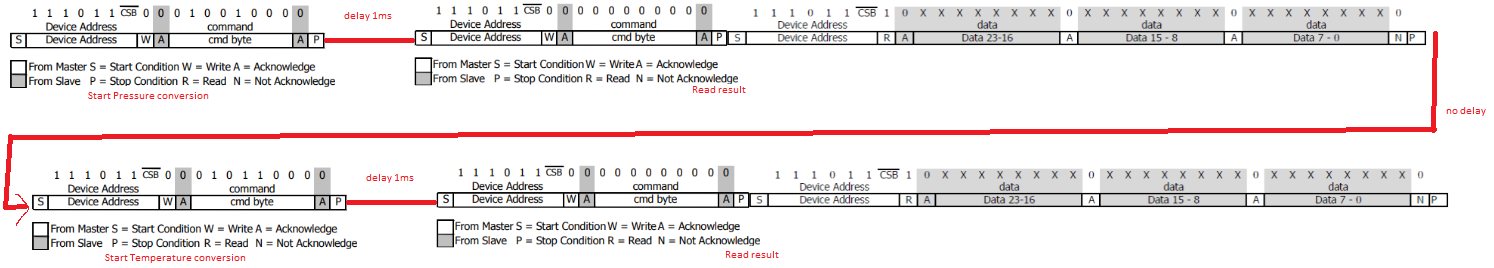
The question is, how do we implement the 1ms delays in step 2 and 5?
PS: We are using the latest C++ SDK.
Cheers,
Blake
https://mbientlab.com/cppdocs/0/timer.html
Hello Eric,
As you suggested, I use timer to implement delay. So here is my implementation, I have an overall timer firing every 4 ms, and this overall timer triggers the other four sub timers to do two i2c reads, two i2c writes. Here is my question -
Is there a way to create a timer with a period of less than 1 ms? As I would like to have a 0.5 ms delay if possible.
With these 5 timers implementation, the board is not very stable. After several logging / downloading sessions, the board stops responding. We have to re-power the board to get it working again. Here is my cleanup sequence before start logging
mbl_mw_logging_stop(board)
mbl_mw_metawearboard_tear_down(board)
mbl_mw_logging_clear_entries(board)
mbl_mw_macro_erase_all(board)
Is it because we didn't do the clean-up properly?
Cheers,
Blake
No
Either reset the board after each session, or partition your script such that it can separately setup a board and collect data.
Implement a retry loop or program the button to stop the sensors when pressed.