I2C Bus Implementation in Python

Hi, I have been having issues with the I2C bus communications with an external sensor. Upon further investigation, I realised the problem was due to SCL and SDA not being aligned - The SCL clock seems to be slightly later than SDA.
My code is as follows:
device_addr = 0xFF
register_addr = 0x12
value = c_uint8(0x90)
libmetawear.mbl_mw_i2c_write(device.board, device_addr, register_addr, byref(value), 1)
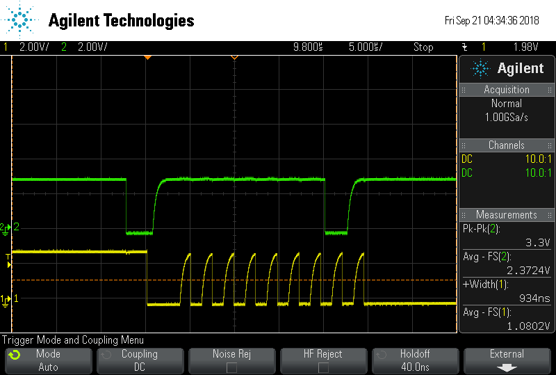
The image below is what I obtain for sending the above code (0xFF as device address)
SCL(YELLOW)
SDA(GREEN)
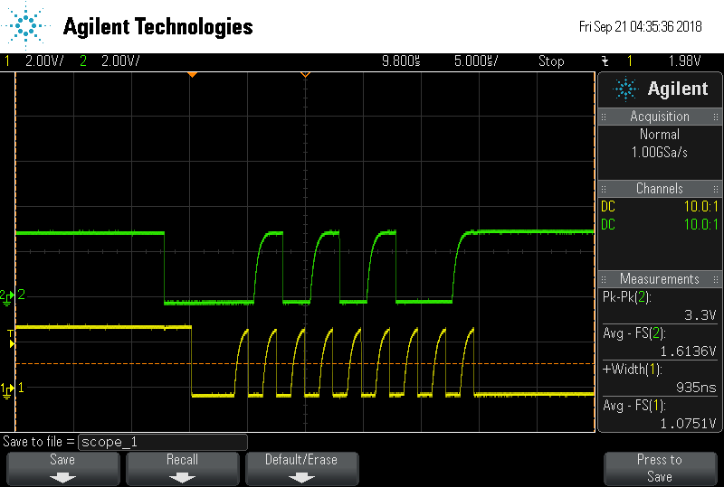
The image below is what I obtain for sending the exact same code with a different device address - 0b10101010.
SCL(YELLOW)
SDA(GREEN)~~~~
Could someone please let me know if it's a firmware, or hardware issue? I'm really confused at this moment.
Warmest Regards,
Daryl
Comments
What external sensor are you connecting to?
Hi Eric,
I'm interfacing this with a LMP91000EVM - a gas sensor. (http://www.ti.com/lit/ds/symlink/lmp91000.pdf)
I'm getting these SCL and SDA signals when it is connected, and when it isn't connected.
My full code as attached:
Daryl
Hi Daryl,
The I2C transactions look correct for the address byte.
One key thing about I2C is that the address is only 7 bits, and the 8th bit is the R/Wb bit. Because the command was a write command the 8th bit is 0, which is why it seems like the clock is shifted.
The 9th clock cycle is for an ACK (acknowledge) from the slave, so the master knows if a slave exists at that address and the message is received. In your captures, there is no ACK (its active low), so the master assumes there is no slave and that is the end of the transaction.
I have a couple ideas as to why your sensor is not ACKing:
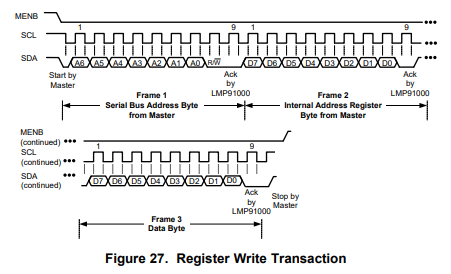
1. MENB must be pulled low (permanently is okay) as in the timing diagram
2. The device address is 1001000 so it is not responding
3. MetaWear uses 400kHz for I2C and the LMP specs 100kHz
I would verify 1 and 2 first, often 100kHz devices will respond to 400kHz. The bit ordering can sometimes be confusing so you may need to try reversing the address bits as well.
Which sensor model are you working with?
Assuming all the pins have been double checked, power verified, etc.
Hi Matt,
Thanks for your help! As is it, I was handling the R/W bit in the address expecting that to be correct, and was wondering why the right shifted version was working fine.
To clarify for others, the I2C address of the sensor I was using is 7 bits long (0b1001100).
As the datasheet mentioned a R/W bit, I handled it myself in the address by sending (0b10011001 or 0x90). This didn't work.
Attempting to send (0b01001100 or 0x48) gave an acknowledgement that continued the write command.
Once again, thanks for your help!
That's great! We'll take a look at how we can clarify the documentation.
Hi,
I have another question regarding the i2c read in python.
The code snippet for the read(got it from the i2c_test.py example) is as shown below. I initially tried to pull read commands from this, but was unable to get effective data.
My question is;
What is the purpose of the ID byte in mbl_mw_i2c_get_data_signal ?
Is the code above correct? I don't seem to be able to pull values from this with the print command.
Daryl
See these sections of the documentation:
https://mbientlab.com/cppdocs/0/mblmwdatasignal.html#readable-signals
https://mbientlab.com/cppdocs/0/i2c.html#read
ID is just a way to distinguish which data corresponds to what i2c signal.
Hi Eric,
Thanks for this, that answers all my questions.
Daryl