Sensor fusion reference frame

I'm trying to get a 2 sensor solution working with sensor fusion. After successfully calibrating them, I have expected them to output quaternions in the same reference frame. (I.e. give the same quaternions when they are oriented the same way.) This was not the case. Please see these images:
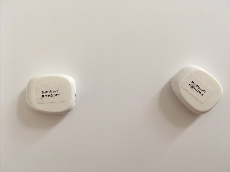
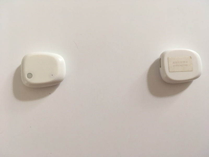
The sensor pairs on the images are oriented so that they output the same quaternions, with around 0.001 accuracy on each of the quaternion's components. This is obviously not good, as they have visibly different orientations.
The table is made from wood. The closest metal was a laptop, around 25 cm away.
Sensor model: MetaMotion R
Model number: 5
Firmware: 1.4.5
Hardware: 0.4, 0.3
C++ SDK: 0.18.4
iOS SDK: 3.3.0 (I'm aware it isn't released to Cocoapods.org yet.)
Can you please advise on how to debug this issue?
In case this is related to sensor calibration, please find below the sequence of SDK calls that we're doing to get the mismatching quaternions.
Pairing (first sensor, then second)
1. Bluetooth scan until an as-yet unpaired sensor is found with rssi > -75. Once found, stop the scan.
2. MetaWear.connectAndSetup()
3. MetaWear.clearAndReset(), then wait for the sensor to disconnect.
4. MetaWear.connectAndSetup() again.
5. MetaWear.remember()
6. mbl_mw_sensor_fusion_stop() (just in case, even though sensor fusion probably wasn't running.)
7. MetaWear.flashLED(color: ..., intensity: 1, _repeat: 5, onTime: 500, period: 1500)
Calibration
1. Bluetooth scan for paired sensors. (It always found the 2 sensors in the test.)
2. MetaWear.connectAndSetup() (first sensor, then second. Skipped if MetaWear.isConnectedAndSetup is true.)
3. mbl_mw_led_stop_and_clear(board)
4. Call mbl_mw_sensor_fusion_calibration_state_data_signal(board) to retrieve the calibration state signal.
5. Record a calib_start macro with the following operations if it wasn't recorded. If it's recorded already, do nothing:
mbl_mw_sensor_fusion_set_mode(board, MBL_MW_SENSOR_FUSION_MODE_NDOF)
mbl_mw_sensor_fusion_set_acc_range(board, MBL_MW_SENSOR_FUSION_ACC_RANGE_16G)
mbl_mw_sensor_fusion_set_gyro_range(board, MBL_MW_SENSOR_FUSION_GYRO_RANGE_2000DPS)
mbl_mw_sensor_fusion_write_config(board)
mbl_mw_sensor_fusion_start(board)
var pattern = MblMwLedPattern()
mbl_mw_led_load_preset_pattern(&pattern, MBL_MW_LED_PRESET_SOLID)
mbl_mw_led_write_pattern(board, &pattern, MBL_MW_LED_COLOR_RED)
mbl_mw_led_play(board)
6. Record a calib_end macro with the following operation if it wasn't recorded. If it's recorded already, do nothing:
mbl_mw_sensor_fusion_stop(board)
7. mbl_mw_datasignal_subscribe(signal, contextPtr, receivedData) with the calibration state signal. (both sensors)
8. Execute the calib_start macro. (both sensors)
9. mbl_mw_datasignal_read(signal) around every 500 milliseconds with the calibration state signal. (both sensors)
10. Wait until all 3 fields in the periodically received calibration state are SENSOR_FUSION_CALIBRATION_ACCURACY_HIGH for a sensor.
12. mbl_mw_datasignal_unsubscribe(signal) with the calibration state signal. (for the sensor that's done)
13. Execute for the sensor that's done:
mbl_mw_led_stop_and_clear(board)
var pattern = MblMwLedPattern()
mbl_mw_led_load_preset_pattern(&pattern, MBL_MW_LED_PRESET_SOLID)
mbl_mw_led_write_pattern(board, &pattern, MBL_MW_LED_COLOR_GREEN)
mbl_mw_led_play(board)
14. mbl_mw_sensor_fusion_read_calibration_data(...) to receive the calibration data, then wait for it to get the result.
15. Execute the calib_stop macro. (for the sensor that's done)
16. Wait for all sensors to be done, then
mbl_mw_led_stop_and_clear(board)
mbl_mw_sensor_fusion_write_calibration_data(board, &calibration)
I'm aware that the recommended way to store the calibration data is to create an on-boot macro with it. I intend to implement it, once I can see the system functional and working. For now, I guess this should work.
Test
1. For the first sensor, then the second:
mbl_mw_led_stop_and_clear(board)
mbl_mw_sensor_fusion_clear_enabled_mask(board)
mbl_mw_sensor_fusion_enable_data(board, MBL_MW_SENSOR_FUSION_DATA_QUATERNION)
qSignal = mbl_mw_sensor_fusion_get_data_signal(board, MBL_MW_SENSOR_FUSION_DATA_QUATERNION)
2. Then I set up the following data processor chain for both sensors: qSignal -> Sample(binSize: 0) -> Time(mode: absolute, period: 25ms) -> Passthrough(mode: conditional, count: 0) -> Log
I'm fully aware that it doesn't make much sense for this test. The binSize parameter of the Sample data processor and the Passthrough's count is adjusted for other implemented use cases. I described the full data processor chain for the sake of completeness. There is no other on-sensor programming done. (I expect the binSize=0 to just let the data through without delaying it.)
3. mbl_mw_sensor_fusion_start(board) for both sensors
4. mbl_mw_datasignal_subscribe(signal, contextPtr, receivedData) for the Time(mode: absolute, period: 25ms) signal created above.
5. print data.valueAs() as MblMwQuaternion values to the console for both sensors as soon as they're received.
Please note that all sensor-related code runs on MetaWear.apiAccessQueue, which is a serial queue, so even operations that I've noted as parallel above really run sequentially. I don't think that this is a multithreading-related issue. I also verified that the order of operations is in fact as I noted above.
Comments
This unresolved issue may be related: https://mbientlab.com/community/discussion/3166/quaternons-different-values-for-same-orientation
Orientation: https://mbientlab.com/tutorials/Orientation.html
Thank you for reading through the lengthy post, Laura!")
The link that you've posted shows very basic information about the reference frame fixed to the sensor. It doesn't answer my question at all. I accidentally opened this post in the General category, but I believe it should've gone to the Requests & Bug Reports category instead.
To summarize my question/bugreport again very briefly:
I understand that the
quaterniondata streamed by the sensor is the relative orientation of the reference frame fixed to the sensor, with respect to a global reference frame. This global reference frame is what's differentiating the NDoF sensor fusion mode from the other sensor fusion modes. It's supposed to be fixed to Earth, and it's usually determined by the direction of the magnetic North.If the sensors are properly calibrated, and there is no magnetic interference nearby, this global reference frame is supposed to be the same for multiple sensors, allowing us to interpret data from 2 or more sensors together. Otherwise, we cannot calculate something as simple as an elbow bend, as it requires 2 sensors and their relative orientation.
What my post is about, is that I think I've properly calibrated 2 sensors, and there is no magnetic interference nearby, yet 2 sensors usually don't output quaternions in the same (global) reference frame. This effectively reduces Mbient to a 1-sensor only system.
The rest of the lengthy post is just information for an engineer, who may be able to pinpoint an error in the Mbient SDK calls, or may confirm that this indeed seems correct and the issue happens somewhere else.
Or they may confirm that 2 sensors aren't supposed to have a common reference frame with Mbient. (This, I think, is unlikely.)
Hi @kustra, thank you for your detailed report.
The process you describe looks sufficient for readout and loading of calibration data.
Can you confirm that during calibration, the sensor was put into a variety of physical orientations for calibration of the magnetometer?
After the calibration data has been loaded, and sensor fusion is re-activated and running, does the device still report high calibration accuracy?
Could you provide raw magnetometer data from your sensor, in a couple different orientations? (with the same settings used to feed NDoF)
Are these sensors configured with any peripheral attachments, such as a vibration motor?
The devices should report a common reference frame, of which the magnetometer is the most significant contributor.
Regards, Matt
It was. We followed the instructions outlined in the Bosch tutorial video. In particular, we held the sensors one by one in hand and moved them in an infinity pattern until the magnetometer calibration state reached high accuracy at least once. (No rings or bracelets closeby.)
We noticed that while the accelerometer and gyroscope calibration state usually only goes up during calibration, the magnetometer calibration state tends to jump back to
unreliableeven after reachingmediumandhighonce. Also, once we stop moving the sensor around, it just jumps back tounreliablewithin 1 second, and stays there.Not for the magnetometer, usually.
For the accelerometer and the gyroscope, calibration state usually stays
highonce it reacheshigh, even if I stop and restart the calibration. But the magnetometer calibration state usually drops back tounreliablefor the next calibration. (Not always, though.)Sure, I'll post some data later today.
I'm not sure what you mean. We use the sensors ordered on the website: https://mbientlab.com/metamotionr/
These sensors contain a vibration motor. I didn't know that you could order sensors without it. We don't use any peripherals external to the sensor's case.
This is good to know for sure. Thank you for the info.
Raw magnetometer output from 2 sensors:
Sensor-bound Z axis is pointing up:
Rotating the sensor +90° around the Z axis:
Rotating the sensor another +90° around the Z axis:
Rotating the sensor -90° around the X axis, so that now -Y is pointing up:
I see. That
-2048is probably not correct. Maybe some of the sensors are faulty? I'll redo my original test with sensors that provide realistic values.I tested the possibly faulty sensor with the Metabase app as well. It seemed to give equivalent output. I attached a short magnetometer stream output and the diagnostic json to this post.
(The outputs are from
mbl_mw_mag_bmm150_get_b_field_data_signal.)2 out of 8 sensors turned out to be working. The rest displayed the same behaviour.
Those two that did work sent orientation data in the same global reference frame.
I figured that this could be related to another issue that I've experienced, but it happens with the 2 good sensors, too: around 2 out of 5 times the sensor unexpectedly disconnects a few seconds after calling
mbl_mw_sensor_fusion_write_calibration_data. To be more precise, if I repeat the calibration flow described above a few times, sometimes (usually soon) I see the sensors randomly disconnecting. If I remove thembl_mw_sensor_fusion_write_calibration_datacall, it never disconnects.Do you have an idea why it happens?
@kustra
Approximately 2048 is the saturation value of the magnetometer (the z has more compensation and is a slightly different sensor than x/y). This means a fixed magnet is exerting a field that exceeds the measurement range of the sensor. As a result it cannot be calibrated effectively.
This may be associated with the vibration motor -- we have recently switched vendors and have had some sightings.
If it is related to the motor, I am surprised to see that two of the units do not show any signs of a nearby fixed magnet (they have vector magnitude on the order of 50uT which is the strength of Earth's magnetic field). Could you confirm confirm whether the good units are equipped with motors?
Regarding the calibration data write disconnect, we have not seen this behavior. Its possible that bad calibration data might crash the sensor fusion subsystem, or the write is being received when the sensor fusion system is not in the correct state. We would need a detailed enough set of steps or code to reproduce the issue on our end.
Matt
@Matt I can confirm that for the good units,
mbl_mw_metawearboard_lookup_module(board, MBL_MW_MODULE_HAPTIC) == 0, which is supposed to mean that the haptic feedback motor is present. (-1means N/A.)A possibly related issue: when we received the sensors, the vibration motor worked perfectly. Now, I cannot get it to work at all, on any of the sensors. I remember adding the relevant function call to the code of our app, then playing around with the threshold that I've used for haptic feedback. Then around 1 month later, it didn't work anymore. So I did a git checkout at the commit where I first introduced haptic feedback, tested it, and it didn't work either. Curious.
We did a firmware update from 1.4.4 to 1.4.5 in the meantime, so this would be my primary suspect for the issue, but there's no way to test as I don't have access to sensors with older firmware.
Regarding the calibration data write disconnect, I didn't experience it with the 2 good sensors in the past few weeks. Maybe testing with the bad sensors destabilized the iOS BLE stack. I'll let you know if I experience it again and find a way to reproduce it. The bad-magnetometer sensors turned out to be rather unstable. E.g. when first streaming sensor fusion quaternions, they produce some kind of data, but upon stopping the stream, and starting again, they produce no data at all, so any business logic that waits for the first quaternion to arrive just hangs.
Let me be a bit more precise: haptic feedback works for 1 sensor out of 8. I added a
mbl_mw_haptic_start_motor(board, 100, 1000)at the end of our pairing process. (See the Pairing section in my first post above.)It works every time with 1 of the sensors, and never with the others. It's one of the sensors with the magnetometer issue.
We ordered 6 more sensors, and they arrived a few days ago. I unboxed them and tried pairing them. Haptic feedback works for these as well.
To me, this means that the vibration motor got faulty in 7 of our 8 old sensors in a few months. To the best of my knowledge, they weren't handled roughly.
I just tested the 6 new sensors that arrived a few days ago. All (!!!) of them have the same magnetometer issue.
I literally just took them from an empty office table with no strong magnets nearby, unboxed the UPS package, then checked out the raw magnetometer output. And the same constant -2048 output happens.
Maybe something happens to them during shipping. But this is really hindering our work. We have bought 14 sensors to date, and 12 of them are faulty out of the box.
@kustra
Note that the haptic module will be present on any board with the drive circuitry, regardless of whether or not a motor is attached -- it is not an indication of the presence of a motor.
We will run some additional firmware tests on the haptic module to see if any issue has been introduced. The module was updated to allow vibration events to be turned off early or extended in duration. It maybe the that the way your code is using the haptic API is not interacting properly with the new implementation.
It is extremely unlikely that 7 units have suddenly developed hardware issues.
I apologize if it wasn't clear in my previous message -- any unit equipped with a vibration motor will have large fixed magnetic fields that interfere with the magnetometer. Any new units with a vibration motor will show the same issue. The vibration motor should not be equipped when magnetometer modes are required. Please talk with hello@mbientlab.com about this.
Matt
Is it safe to remove the vibration motor from the board to resolve this issue?
Yes, it is safe if you have experience soldering (using a soldering iron).
You can also cut them off just make sure the leads aren't exposed (there should not be any exposed metal or it will create issues).