Sensor Fusion Settings
Sensor fusion modes are meant to calculate measures describing the orientation of the MetaWear device in space. It can be distinguished between non-absolute or relative orientation and absolute orientation. Absolute orientation means orientation of the sensor with respect to the earth and its magnetic field. In other words, absolute orientation sensor fusion modes calculate the direction of the magnetic north pole.
In non-absolute or relative orientation modes, the heading of the sensor can vary depending on how the sensor is placed initially.
All fusion modes provide the heading of the sensor as quaternion data or in Euler angles (roll, pitch and yaw angle). The acceleration sensor is both exposed to the gravity force and to accelerations applied to the sensor due to movement. In fusion modes it is possible to separate the two acceleration sources, and thus the sensor fusion data provides separately linear acceleration (i.e. acceleration that is applied due to movement) and the gravity vector.
Note
Note 1: The sensor fusion algorithm performs automatic background calibration of all sensors. This feature cannot be disabled.
Note
Note 2: The sensor fusion algorithm uses the accelerometer data to compensate for the gyroscope drift over time. When the device is in motion, the accelerometer data is temporarily ignored and the fusion relies on the gyroscope for pitch and roll. If the accelerometer data cannot be used for an extended period of time (e.g. due to vibration, or to constant movement), then this may cause the pitch and roll values to drift over time. Likewise, if the magnetometer data is detected to be distorted, it will automatically be ignored by the algorithm and this may cause the heading to drift over time (as in IMU mode).
Note
Note 3: The sensor fusion algorithm was primarily designed to track human motion. If the device is subjected to large accelerations for an extended period of time (e.g. in a vehicle cornering at high speed or braking over a long distance), the device may incorrectly interpret this large acceleration as the gravity vector. For applications where the sensor may be exposed to significant velocities, it is recommended to test the device for the specific use-case.
Modes
The sensor fusion algorithm has 4 fusion modes, listed in the below table:
Mode |
Description |
|---|---|
NDoF |
Calculates absolute orientation from accelerometer, gyro, and magnetometer |
IMUPlus |
Calculates relative orientation in space from accelerometer and gyro data |
Compass |
Determines geographic direction from th Earth’s magnetic field |
M4G |
Similar to IMUPlus except rotation is detected with the magnetometer |
Data
The sensor fusion algorithm provides raw acceleration, rotation, and magnetic field values along with quaternion values and Euler angles. Furthermore, the source of acceleration can be separated into gravity and linear acceleration and both values are also provided. Keep in mind that each sensor fusion mode has different sets of available data and produces it at different rates.
Mode |
Acc |
Gyro |
Mag |
|---|---|---|---|
NDoF |
100Hz |
100Hz |
25Hz |
IMUPlus |
100Hz |
100Hz |
N/A |
Compass |
25Hz |
N/A |
25Hz |
M4G |
50Hz |
N/A |
50Hz |
NDOF
This is a fusion mode with 9 degrees of freedom where the fused absolute orientation data is calculated from accelerometer, gyroscope and the magnetometer. The advantages of combining all three sensors are a fast calculation, resulting in high output data rate, and high robustness from magnetic field distortions. In this mode the Fast Magnetometer calibration is turned ON and thereby resulting in quick calibration of the magnetometer and higher output data accuracy.
IMUPlus (IMU - Inertial Measurement Unit)
In the IMU mode the relative orientation of the device in space is calculated from the accelerometer and gyroscope data. The calculation is fast (i.e. high output data rate).
Compass
The COMPASS mode is intended to measure the magnetic earth field and calculate the geographic direction.
The earth magnetic field is a vector with the horizontal components x,y and the vertical z component. It depends on the position on the globe and natural iron occurrence. For heading calculation (direction of compass pointer) only the horizontal components x and y are used. Therefore the vector components of the earth magnetic field must be transformed in the horizontal plane, which requires the knowledge of the direction of the gravity vector. To summarize, the heading can only be calculated when considering gravity and magnetic field at the same time.
However, the measurement accuracy depends on the stability of the surrounding magnetic field. Furthermore, since the earth magnetic field is usually much smaller than the magnetic fields that occur around and inside electronic devices, the compass mode requires calibration (see chapter 3.10)
M4G (Magnet for Gyroscope)
The M4G mode is similar to the IMU mode, but instead of using the gyroscope signal to detect rotation, the changing orientation of the magnetometer in the magnetic field is used. Since the magnetometer has much lower power consumption than the gyroscope, this mode is less power consuming in comparison to the IMU mode. There are no drift effects in this mode which are inherent to the gyroscope.
However, as for compass mode, the measurement accuracy depends on the stability of the surrounding magnetic field. For this mode no magnetometer calibration is required and also not available.
Warning
Make sure the devices is calibrated and the magnetometer is as far away from magnets as possible as it is used to compensate from drift in this mode.
Recommendations
APIs
When using the sensor fusion module, do not use the accelerometer, gyro, and magnetometer functions. The api will automatically configure the sensors based on the selected fusion mode (data rates/sampling rates.)
Magnets and Magnetometers
Magnets in the surroundings will affect the magnetometer. This includes the battery, the coin vibration motor, and even items such as computers, jewelery or phones. Keep the device away from large electrical currents, and metal objects. Large buildings also often contain a steel structure which distorts the magnetic field. If you cannot ensure that your surroundings will be magnet free, we recommend that you do not use the M4G or NDoF modes.
Calibration
Always make sure your device is calibrated and calibrate it as often as possible. See our Calibration section.
Once you receive the calibration status 3 on all 3 sensors, the device is fully calibrated.
The offsets are updated once the calibration procedure is complete. These offsets can be saved on the non-volatile memory using our Macros.
Modes
In NDOF mode, pitch and roll drift and compensated by the accelerometer sensing earth’s gravity, and heading drift is compensated by the magnetometer sensing earth’s magnetic field. In this mode, it is very important that the magnetometer be free of disturbing magnetic fields and the calibration be 3/3 for the magnetometer and the gyroscope. This is a great all purpose mode for many applications that require heading and orientation.
In NDOF mode, after magnetic calibration is complete the heading will be 0 degrees when facing magnetic North.
To validate that the sensor is operating properly, you can rotate it until it shows 0 degree heading and place a compass nearby. They should point the same direction. If this is not magnetic North, then the field is distorted in the location you are (usually indoors is not very reliable).
In case of relative heading, the IMU mode is a good choice, but only for a limited amount of time. If the device will be in use for multipe hours, then the use of a magnetometer (or other) is paramount to calibrate the inherent heading drift with the integration of the gyroscope signal. Typically, the magnetometer data is used, but in cases where the magnetic field cannot be trusted, heading can be compensated with a GPS system, or complemented with cameras to name a few methods of compensation.
If the rotation speed of the device does not exceed a few degrees per second, then the gyroscope is not necessarily required, and heading can be derived from accelerometer and magnetometer only (Compass and M4G modes)
Drift
Most of what you see as “drift” is typically heading drift.
No matter what underlying technology, there will always be a drift when integrating the gyroscope data to get heading. The main factor for this drift is the bias stability. With the BOSCH sensor fusion algorithm and sensors, it is already close to the maximum stability allowed for a consumer electronic device.
Sensors that are more precise than this are subject to export control (and VERY expensive - think aviation $$$).
In IMU mode, when the device is in motion, the pitch & roll drift are compensated dynamically by the accelerometer, but the heading drifts over time. The amount of drift varies on a lot of factors.
When you place the device on the table, the sensor fusion algorihtm automatically detects this and stops integrating the data coming from the gyroscope to prevent drift.
Minimizing turns in your application also help combat drift.
Outputs
If you are designing a sensor solution for a system that has a limited range of motion, you can use Euler angles. But if you are designing a sensor that can be oriented anywhere in space, you should use quaternions.
Euler Angles
The Euler angle output is designed for applications which need a quick reference to the heading, pitch and roll values, for application where the tilt angles are less than 30 degrees. A typical application would be a digital compass, where the device should be almost parallel to the ground, and the heading output is used. Other applications could be pitch and roll monitoring for remote controlled cars, where it is expected that the device orientation stays the same.
Euler angles are not well suited for describing complete rotations, since when the pitch is 90 degrees, heading is undetermined. The device automatically changes the reference frame for the Euler angle output, so that no matter in which orientation it is mounted in the device, the output can be used directly. This causes discontinuities when making full rotations.
The device can be used in application where complete 3D rotations needs to be measured, in which case the recommended sensor output to use is the Quaternion output.
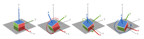
Euler angles allow for simple visualization of objects rotated three times around perpendicular axes (x-y-x, x-z-x, y-x-y, y-z-y, z-x-z, z-y-z, x-y-z, x-z-y, y-x-z, y-z-x, z-x-y, z-y-x).
As long as the axes stay at least partially perpendicular, they are sufficient. However, as the axes rotate, an angle exists where two axes can describe the same rotation—creating a condition known as gimbal lock. When gimbal lock occurs, it is impossible to reorient without an external reference.
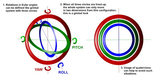
The problem of gimbal lock does not exist when using quaternions.
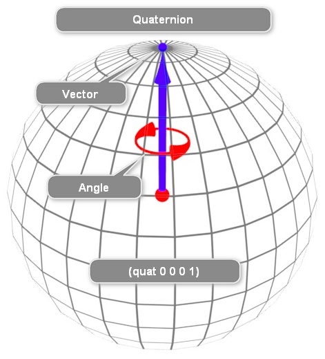
Quaternions
A quaternion consists of four numbers: a scalar and a three-component vector.
where w, x, y, and z are all real numbers and i, j, and k are quaternion units.
These four numbers succinctly reorient vectors in a single rotation with or without changes in length.